Abbess Chiller C80-4HP – Plate profile testing
C80-4 Plate Profile Temperature and Wattage Differential
- Bath is set to -95C, with 20 gallons of heat exchange fluid, Plate initial temperature: 100C
- Oil is circulating to plate via proportional valve
- 40C degree step intervals, 60 min soak time, rate: 1 degree/min
- Load: 22”x22”x0.75” (T6061) Aluminum plate (~16kg) in a 24” Cube vacuum chamber
- Aluminum plate is equipped with resistance heater rods. Copper tubing is clipped into the slotted plate for cooling
Graph 1 does a step by step profile of a 16kg aluminum plate as it cools from 100C to -88C at 1C/min and is then heated at 1C/min back too 100C. This profile holds for an hour at 40C increments on both the cool-down and heat-up of the plate. Cooling and heating power are pulsed by the PID controller in order to maintain setpoints and ramp rates. Wattages are negative during cooling and positive during heating. The temperature of the bath sees nearly no change from this type of profile. In this test the oil bath is precooled to -95C before the profile is run. The differential wattage is calculated based on the rate of temperature change of a plate with a known mass and represents the useful cooling or heating provided by the system at a given temperature. This test is a good representation of a complex temperature profile consisting of MULTIPLE SETPOINTS across a BROAD RANGE OF TEMPERATURES.
Abbess Chiller C80-4HP – Plate profile testing
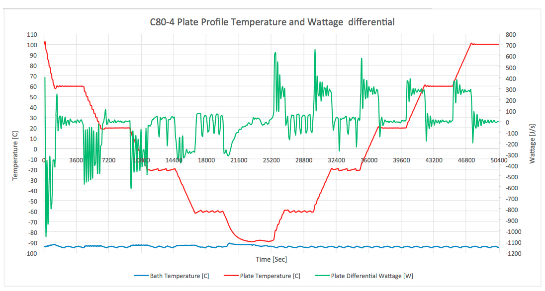
C80-4 Plate MinMax Profile Temperature and Wattage Differential
- Bath is set to -95C, with 20 gallons of heat exchange fluid, Plate initial temperature: 100C
- Oil is circulating to plate via proportional valve
- Cooling from 100C to -88C at maximum rate, Heating from -88C to 100C maximum rate
- Load: 22”x22”x0.75” (T6061) Aluminum plate (~16kg) in a 24” Cube vacuum chamber
- Aluminum plate is equipped with resistance heater rods. Copper tubing is clipped into the slotted plate for cooling
Graph 2 shows the maximum cool down ramp from 100C to -88C of a 16kg aluminum plate followed by a maximum heating of that plate via thermal heating rods. Heat transfer rates (given in watts), are negative during cooling and positive during heating of the plate. In this test the oil bath is precooled to -95C before he profile is run. In this test the oil bath is precooled to -95C before the profile is run. This test is ideal for THERMAL SHOCK applications.
Abbess Chiller C80-4HP – Plate profile testing
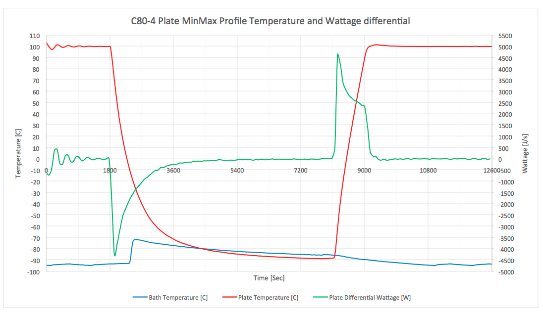
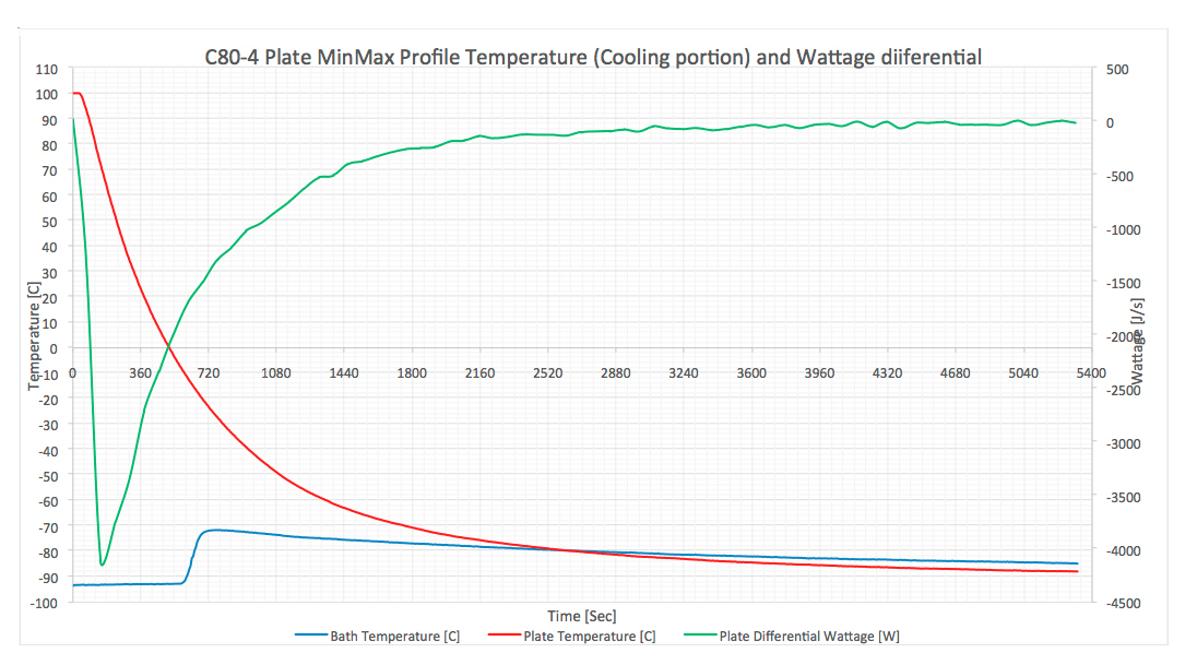
C80-4 Plate MinMax Profile Temperature (Cooling Portion) and Wattage Differential
- Bath is set to -95C, with 20 gallons of heat exchange fluid, Plate initial temperature: 100C
- Oil is circulating to plate via proportional valve
- Cooling from 100C to -88C at maximum rate, Heating from -88C to 100C maximum rate
- Load: 22”x22”x0.75” (T6061) Aluminum plate (~16kg) in a 24” Cube vacuum chamber
- Aluminum plate is equipped with resistance heater rods. Copper tubing is clipped into the slotted plate for cooling
Graph 3 shows the maximum cool down curve of a 16kg aluminum plate from 100C to -88C in a vacuum chamber. The Plate temperature drops quickly as oil at -95C is first pumped through the plate reaching a maximum cooling wattage of about 4200 Watts at about 70C. Once the plate temperature dips below freezing the warmer oil that is dumped into the top of the tank begins to reach the temperature sensor mid way through the sealed bath which is stratified in temperature. Heat transfer slows as the difference between the plate and oil temperature shrinks. The plate reaches a temperature of -80C in just under 45 minutes where the heat transfer rate slows to about 200 Watts. This wattage is only representative of the plate’s temperature change rate and does not represent the plate’s ability to absorb additional load.
Abbess Chiller C80-4HP – Plate profile testing
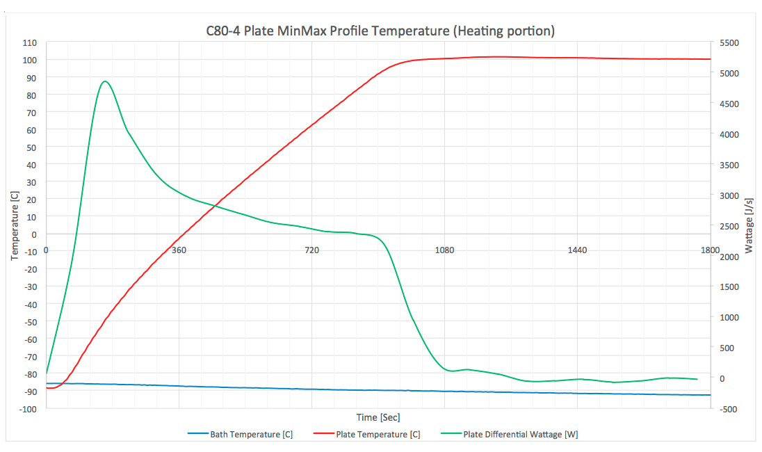
C80-4 Plate MinMax Profile Temperature (Heating Portion)
- Bath is set to -95C, with 20 gallons of heat exchange fluid, Plate initial temperature: 100C
- Oil is circulating to plate via proportional valve
- Cooling from 100C to -88C at maximum rate, Heating from -88C to 100C maximum rate
- Load: 22”x22”x0.75” (T6061) Aluminum plate (~16kg) in a 24” Cube vacuum chamber
- Aluminum plate is equipped with resistance heater rods. Copper tubing is clipped into the slotted plate for cooling
Graph 4 shows the maximum heating capability of the thermal plate via heating rods. The chiller is in bypass mode during this operation so the bath continues to cool during this section of the profile. This curve only represents the power of the heating rods in the plate and does not reflect any chiller performance.
Abbess Chiller C80-4HP
Proportional Valve Fully Opened Bath Controlled Test (Heating & Cooling)
- Proportional Valve is manually opened via temperature controller (Fully Opened 100%)
- Oil is circulating through the plate throughout the test, heating with heater rod inside of bath, cooling by cascade refrigeration system
- Cooling from 100C to -88C at maximum rate, Soak at 100C for 1 hour, Heating from -88C to 100C maximum rate
- Load: 22”x22”x0.75” (T6061) Aluminum plate (~16kg) in a 24” Cube vacuum chamber
- Aluminum plate is equipped with resistance heater rods (Not used for this test). Copper tubing is clipped into the slotted plate for cooling
Graph 5 showing a profile in which the temperature of the plate is controlled solely by the circulating fluid. The oil is heated to 100C in order to heat the thermal plate. The temperature of the oil is then held at 100C for one hour. The oil and thermal plate are then brought down to -88C together instead of pre-cooling the oil. This form of temperature control would be used in applications where THERMAL UNIFORMITY is needed across the load or when embedded resistive heaters are not available in the load.

Abbess Chiller C80-4HP
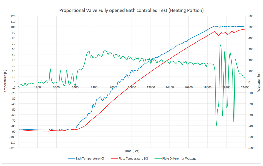
Proportional Valve Fully Opened Bath Controlled Test (Heating Portion)
- Proportional Valve is manually opened via temperature controller (Fully Opened 100%)
- Oil is circulating through the plate throughout the test, heating with heater rod inside of bath, cooling by cascade refrigeration system
- Cooling from 100C to -88C at maximum rate, Soak at 100C for 1 hour, Heating from -88C to 100C maximum rate
- Load: 22”x22”x0.75” (T6061) Aluminum plate (~16kg) in a 24” Cube vacuum chamber
- Aluminum plate is equipped with resistance heater rods (Not used for this test). Copper tubing is clipped into the slotted plate for cooling.
Graph 6 shows a plate that is heated from -88C to 95C by using the resistive heaters in the bath as opposed to resistive heaters in the load.
Abbess Chiller C80-4HP
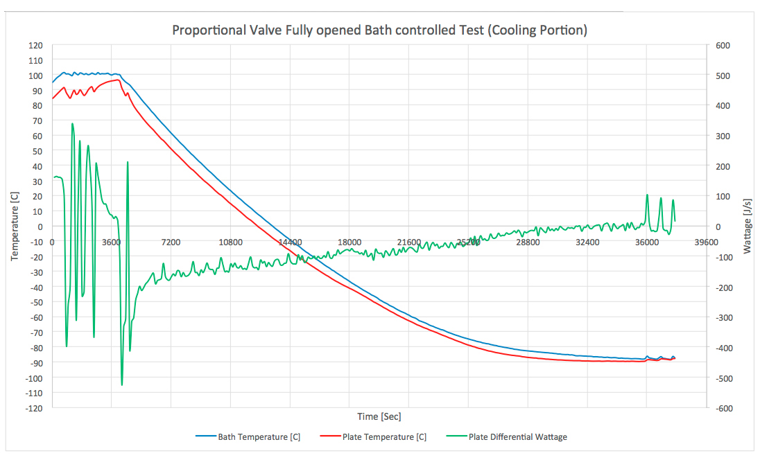
Proportional Valve Fully Opened Bath Controlled Test (Cooling Portion)
- Proportional Valve is manually opened via temperature controller (Fully Opened 100%)
- Oil is circulating through the plate throughout the test, heating with heater rod inside of bath, cooling by cascade refrigeration system
- Cooling from 100C to -88C at maximum rate, Soak at 100C for 1 hour, Heating from -88C to 100C maximum rate
- Load: 22”x22”x0.75” (T6061) Aluminum plate (~16kg) in a 24” Cube vacuum chamber
- Aluminum plate is equipped with resistance heater rods (Not used for this test). Copper tubing is clipped into the slotted plate for cooling
Graph 7 shows the plate being cooled at the same time as the thermal oil bath. This is a slower but more stable way of cooling a load that results in more uniform load temperature gradients. A system using this method of cooling would have a more uniform temperature across the load.