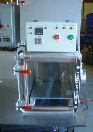
The Thermal Vacuum System allows items placed inside to be exposed to vacuum as well as heat or cooled via the Thermal Plate. The entire system can be controlled manually, by starting/stopping the pump(s) and opening/closing valves. Optionally, a Vacuum Cycle Controller (VCC analog shown) can be used to control some or all of the control functions such as vacuum level, temperature, and time at vacuum.

This Thermal Vacuum Chamber System consists of the following major components:
- Vacuum Chamber – a front loading Stainless Steel Cube
- Thermal Plate – Aluminum/Copper Thermal Plate mounted in the bottom of chamber with heating elements and cooling loop. Feed-through for electrical power, thermocouple and cooling lines extend through the rear wall of the chamber. The thermal plate allows heating/cooling of items in the chamber under vacuum.
- Controlled by PID temperature Controller mounted in Process Control Enclosure. Note: Unless the chamber includes external insulation, the Thermal Plate is intended for use only while under vacuum.
- Mobile Cart – Heavy-duty cart/stand with chamber and pumping system mounted and tested ready to use.
- Vacuum Gauge and Controller
- Temperature Controller, Also provides pressure set-point that can be used for various system control functions.
- Status Indicators – Provide visual indication of system status.
- Vacuum Cycle Controller – Control input buttons, switches, and interfaces to external components. Contains components necessary for controlling the system as well as logic and interfaces
- Control Valves
- Manual Vent Valve – Manual override vent valve allows user to vent air into chamber at end of cycle or in case of power loss or other circumstance where an optional automatic valve is not functioning.
- Automatic Vent Valve – Automatic solenoid valve vents air into chamber based on control input from Vacuum Cycle Controller.


