Abstract
Introduction
Space Simulation Test Systems
Complex Space Simulation System
Conclusions
Abstract
Altitude and Space Simulation vacuum systems are presented that can be configured as test beds for optical systems. These test beds can offer optical testing capabilities at a variety of temperatures and vacuum pressures with PC touch screen GUI control and monitoring.
With the PC Touch Screen Package, the operator is free to define new pressure and thermal setpoints and profiles on the fly. Engineers and their QC departments appreciate the optional features enabled by programming the pc to acquire and log data, and to message operator mobile devices. Engineers may similarly precisely define their procedures by programming in test variables for the operators to execute. In addition, engineers can connect in remotely to reprogram, acquire and log data, and even to operate the system remotely.
Flexibility of design combined with a wide choice of feedthroughs yields versatile, ergonomic, vacuum chamber optical test beds. Incorporation of multiple features broadens the potential use and thus the useful lifetime of the equipment. Engineers are able to plan for, and design-in, a wide range of current and future tests, improving the ROI of the system.
Keywords: Optical Test Bed; Space Simulation; Vacuum Chamber; “Climb & Dive”; “Launch to Space”; Pressure Profiling; Thermal Profiling; Optical Space Systems
1. Introduction
(TOP)
Companies who manufacturer space instrumentation (including satellites themselves) have to subject their products to Prototyping, Flight Qualification, and Flight Verification phases. Before launch, the products must experience space-like temperatures and vacuum levels, and be shown not only to survive the extreme ranges, but also to operate within specification before, during, and after. Space Simulation Chambers are key to these tests, and Abbess Instruments of Holliston, is one of the few companies in the world with the capability to manufacture them.
Others need to subject medical, pharmaceutical, food, electronics, and aerospace products and/or packaging to the minimum or range of pressures that they must survive, and/or operate in, as they are trucked/flown or used around the world at various altitudes. Abbess Instruments has a range of Altitude Test systems capable of addressing DOT and FAA ASTM test requirements.
Abbess Instruments has a wide portfolio of Test systems capable of simulating a variety of vacuums … with or without heat and/or cooling. Abbess defines the Altitude series as being for simulating altitudes from sea-level up to 100,000 ft / 19miles / 30km (i.e. from 760 to 10-4 Torr). The Space Simulation series simulates launch to space pressures, focusing on space vacuums of 10-4 to
10-8 Torr (i.e. altitudes above 100,000 ft).
All of these systems may be fitted with optical ports, sensors and other upgrades (such as power & signal, and mechanical feedthroughs) to facilitate in vacuo optical testing. Of particular import to optical space systems is contamination control capability.
2. Space Simulation Test Systems
(TOP)
Basic Systems
Abbess’ most basic Test Systems (as illustrated in Fig 1) consist of the following, to which the customer integrates their own pumping system:
- Space Simulation Vacuum Chamber
– A front or top-loading Aluminum or SS cube with metal door.
or
- Altitude Test Vacuum Chamber
– A front or top-loading aluminum cylinder with Acrylic or Aluminum lid.
or
– A front or top-loading Aluminum or SS cube with full Acrylic or metal doors.
- Analog Pressure Gauge
Complexity can be added by upgrading to include a pumping system … amongst many other features mentioned later.

Actual chamber material choices are dependent on the desired operational vacuum, as outlined in Table 1.
Manual or automated operation? Abbess works closely with the customer to customize automation to their process, and to ensure the system configuration meets operational needs: While the most basic system (such as in Fig 1) can be controlled manually (by starting/stopping the pump(s) and opening/closing valves), a Vacuum Cycle Controller can be added to automate a) vacuum/hold/vent control functions, and b) vacuum (and thermal) monitoring. Control may be either via panel-mounted buttons and indicators or via a PC with user-specified Graphical User Interface (GUI). The basicdigital VCC will permit a single ‘automatic’ altitude/vacuum set point, (VCC) can be added to automate a) vacuum/hold/vent whereas full altitude/flight ‘climb & Dive’ profile simulation functionality can be built in to the PC Touch Screen VCC upgrade option. While such pressure profiling is not feasible for pressures <10-4 Torr, the PC Touch Screen VCC upgrade option is necessary if thermal profiling is required.
| Material* | Useful Pressure Range (Torr) | Use | Comments |
| Untreated Al with Al or Acrylic door | 760 to 10-4 inc. | altitude testing | More powerful pumps will be needed with an Acrylic door than if a metal door was used. Acrylic door must be kept below 135C. |
| Acid-etched Al chamber & door | 760 to 10-5 inc. | space simulation | |
| Untreated SS chamber & door | 760 to 10-6 inc. | ||
| Electropolished SS chamber & door | 10-6 and better | ||
| Bakeout & Electropolished SS chamber & door | 10-7 and better | Bakeout required to outgas chamber | |
| * If speed of pumpdown is a priority, consider upgrading to the next material choice | |||

Complex Space Simulation System
(TOP)
A complex Space Simulation Vacuum chamber consists of several major subsystems: the main chamber; the pumping system; the thermal shroud (or plate); and the control system:
Chambers can be as large as the ones shown below (in the order of 48” x 48” x 48” or larger) and, for vacuums less than 10-5 Torr, are made from electropolished Stainless Steel. Difficult to machine and weld, the chambers are routinely made so that the walls deflect less than an impressive 1/1000” while under vacuum. Thick walls and strategically placed external ribs are needed to do this – more in the larger chambers. The smallest cube chamber offered is 14”.

Contamination Control management is made possible through a combination of a Bakeout Shroud (bake-out heating elements and jacketed exterior insulation), inert gas purge kit/s, and feedthroughs for QCMs (Quartz Crystal Microbalances). Bakeout also facilitates achievement of high vacuum.
Space Simulation pumping systems are amongst the most complex, often requiring two Turbo pumps in order to bring the expansive chamber down to the required vacuum level … and in a timely fashion. Such pumps attach directly to the chamber and pump through large ports, of around 10” diameter, at speeds of hundreds of cubic feet a minute. A complex pump down is illustrated in Fig 5.
Altitude Test Chamber pumping systems can also be complex, particularly if “Climb & Dive” functionality or operational pressures of ≤10-4 are required.


The thermal shroud is a sub-chamber within the chamber finished perhaps in gold (as shown in Fig. 3) to reflect as much heat as possible back to the Unit Under Test; or dense black to absorb as much heat and light as possible. Shrouds are typically heated and cooled sub-systems covering the large range of -150 °C to +195 °C, with liquid N2 being the most common choice for cooling. Closed loop refrigeration is an optional extra, and limits the lower temperature to -80 °C.
Individual heating and/or cooling thermal plates/shelving with control are available … for heating up to 150 °C, or 300 °C, and/or for cooling to -150 °C (or -80 °C if closed loop refrigeration is used). Multiple thermal plates can be independently and simultaneously controlled to simulate dynamic orbital sun/shade exposure.
Monitoring and control is tailored to the customer’s specified process needs which, for Space Simulation Systems, usually requires a PC Touch Screen package (the panel is shown to the left of Figs. 3 & 4, and its GUI in Fig. 6) – a necessity when “Climb & Dive” and/or thermal profiling is required.
Profiling uses state-of-the art pressure and temperature control techniques and algorithms, as well as accessing full potential of PID controllers and tuning functions. The Touch Screen GUI pressure profile offers a variety of display options: Torr, ft, m.

An example of thermal profiling and plate performance is given in Figs. 7 & 8. Manual and automated valve operation and pump control are configured to both optimize operation time and ensure the proper cycling of vacuum equipment.
With the PC Touch Screen Package, the engineer is free to define new pressure and thermal setpoints and profiles on the fly as test requirements change.
Engineers and their QC departments appreciate the optional features enabled by programming the pc to acquire and log data, and to message operator mobile devices. Engineers may similarly precisely define their procedures by programming in test variables for the operators to execute. In addition, engineers can connect in remotely to reprogram, acquire and log data, and even operate the system remotely.
Abbess has routinely, remotely operated customer’s chambers installed in Europe from the US … including running diagnostics, and updating & modifying programs. This remote feature is not included for customers requiring higher security.
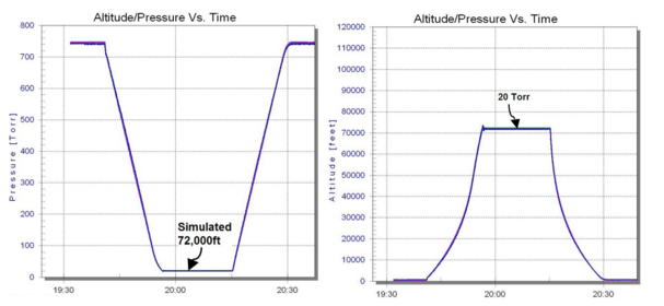
“Climb & Dive” profiles are presented here in Torr and in simulated altitude (feet) for a “Climb & Dive” from sea level to 72,000ft (20 Torr) in a 48” cube chamber. Both ‘simple’ & ‘complex’ profiling produces a linear “Climb & Dive” in Torr. The “Climb & Dive” sample illustrations given here are of ‘simple’ profiling: Note that a simulated “Climb” in altitude presents as a drop/dive in Torr: i.e. pressure drops as altitude increases. The system operates in Torr; any values the operator inputs as feet are converted by the system for monitoring and control purposes. All ramps are linear in Torr, but non-linear in ft or meters (the average ft or m ramp rates achieved are those set by the operator). In ‘complex’ profiling, Abbess software accesses full PID functionality (throughout the full ramp) to achieve linear “Climb & Dive” also in ft and m.


Optical Test Bed
Altitude and Space Simulation Test systems are readily configured as test beds providing optical testing, product visibility, and product accessibility: test items may be visually observed (illuminated by optional, switchable, in-chamber lighting) through optional viewports, as illustrated in Figs. 1, 3, 4, & 11. The same, or other viewports, are used to optically illuminate/test the in- vacuum optical items at desired wavelengths. Optional shutters are closed for subsequent light-tight storage or functional testing. Large doors, and portals/hatches (Fig 11) provide optimal accessibility.
Optional mechanical feedthroughs (such as shafts with or without rotation), and electrical feedthroughs (for power and signal) are incorporated for optical test unit manipulation and operation (Fig 12). High Power, D, Sub-D, SMA, bnc, thermocouples, Ethernet, fibreoptic, and other hybrid hybrid electrical vacuum feedthroughs are all available.
| Complex Space Simulation System Performance 48” Cube | ||
| Operational Vacuum | ≤10-6 Torr | For an empty, clean chamber at sea level … over all Temp ranges |
| Vacuum Ramps | Pump Down Ramp: ≤10-5 Torr in ≤ 3 hrs |
For an empty, clean chamber at sea level |
| Vacuum Relief Ramp: < 3 mins |
||
| Deep Space Vacuum Stability | Within 1×10⁻⁹ Torr over several minutes
Within 0.2×10⁻⁷ over 12h 49m |
Measured at 10-7 Torr |
| Thermal Range | -150 °C to +150 °C | Of thermal plates |
| Thermal Ramps | Fast Ramp: | Over the range -60 °C to +100 °C heating and cooling |
| 3 °C/min | Using 22psi LN2 tanks | |
| 6 °C/min | Using 235 psi LN2 tanks | |
| Slow Ramp: ≤1 °C/min |
||
Where there is limited counter space or large batch sizes, the entire system can be integrated on a cart using identical or mixed-sized, chambers. Since cart mounted systems are shipped turn-key, set-up is minimal. Cart-mounting provides full system mobility and thus flexibility of positioning on your production floor. Mixed-sized inventory? Add optional removable shelving.


3. Conclusions
(TOP)
Successfully test your high-value optical inventory in Abbess manual or ‘automatic’, Altitude or Space Simulation Systems: Test beds can offer testing capabilities at a variety of temperatures (-150 °C to +300 °C) and vacuum pressures (≥10-8 Torr) with PC touch screen GUI control and monitoring. Such control and monitoring provides for vacuum cycle control as well as for other customer-required processes such as heating and cooling. Thermal and pressure setpoint or profiling techniques are available, the latter of which provides for simulated altitude “Climb & Dive”. Setpoint techniques allow the operator to simulate launch to deep space within one test run and within one chamber.
With the PC Touch Screen Package, the operator is free to define new setpoints and profiles on the fly as test requirements change. Engineers and their QC departments appreciate the optional features enabled by programming the pc to acquire and log data, and to message operator mobile devices. Engineers may similarly precisely define their procedures by programming in test variables for the operators to execute. In addition, engineers can connect in remotely to reprogram, acquire and log data, and even to operate the system remotely. Abbess has routinely and remotely operated customer’s chambers installed in Europe from the US … including running diagnostics, and updating & modifying programs.
Flexibility of design combined with a wide choice of feedthroughs yields versatile, ergonomic, vacuum chamber optical test beds. Incorporation of multiple features broadens the potential use and thus the useful lifetime of the equipment. Engineers are able to plan for, and design-in, a wide range of current and future tests, improving the ROI of the system.
ITAR Disclaimer: Some equipment described in this document is subject to the International Traffic in Arms Regulation (ITAR) and is controlled by the export laws of the U.S. Government.